

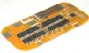
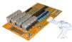
This protection circuit is specially designed for6.4V Li-Ion Battery pack with 5A discharging rate. Differentthannormal PCB, it providesequilibrium function after battery pack is fully charged.PCM will detect each cell’s voltage and trim higher voltage down until other cells reach the same voltagelevel. Therefore,it helpsLi-Ion cells have longer service life.
| Protection Circuit Module Specifications For 6.4V LiFePO4 Battery Pack | |
| Model: PCM-LFP6V5A | |
| Charging Voltage | DC: 7.2V, CC/CV (3.6V/Cell) |
| Balance voltage for single cell | 3.60V±0.03V |
| Balance current for single cell | 33±3mA |
| Over-charge protection voltage for single cell | 3.90±0.025V |
| Over-discharge protection voltage for single cell | 2.00±0.05V |
| Over-current detection protection | 14±2A |
| Maximal continuous Charging & Discharging current | 5A |
| Maximal Current consumption for single cell | ≤20uA |
| Protection circuitry resistance (B- TO P-) | ≤40mΩ |
| Dimension | 65mmx10mmx2mm |
| Weight | 1 gram |
| P+/P-/BM |
P+ = Charge+ / Discharge + |
| Temperature |
Operating Temperature Range: -40 to 85°C |
| Specification | Download Specification |
For other PCM/PCB, please check our PCM/PCB/BMS/CMB/UPS category
Warning
- If you want to use this protection circuit board for a battery that is less than the rated drain, you must add additional protection device to protect the battery itself. Such as: proper rated polyswitch.
- To achieve balance, each cell in battery pack must has equal voltagewithin tolerance. When charger LED turn Green, allow 30 minutes for pack to balance before use.
- You must be professional in Lithium battery pack to buy the protection circuit board. Misusing may cause battery damage or explode.We are not responsible for any damage caused by user.


Reviews
There are no reviews yet.